Simple traffic light circuit diagram Solved block diagram the traffic signal control system Logic circuit traffic signal
Traffic Lights Circuit Design Using Logic Gates - 4K Wallpapers Review
Logic plc programming signal mikrora
Ladder plc logic examples diagram programming symbols motor delay example timer control stop start off motors electrical cooling wire light
Logic circuits and traffic lightsLogic1 flowchart traffic light.pdf - Block diagram of the density based traffic light control systemLogic dsd.
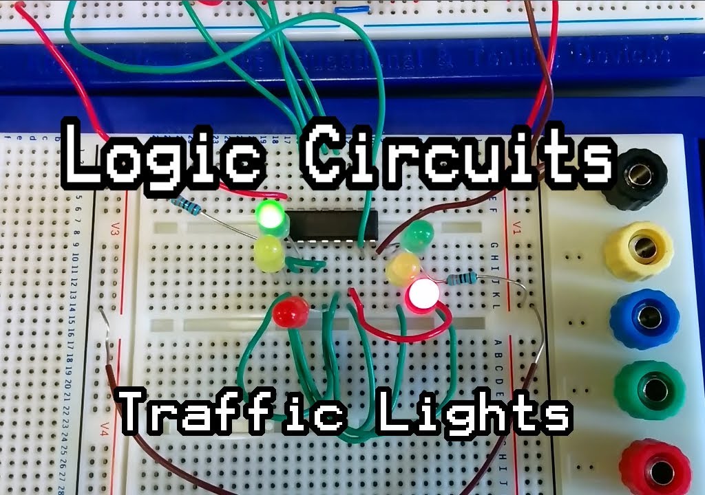
Traffic lights circuit design using logic gatesDsd traffic light controlling with logic gates Solved in this project, you will design a simple trafficTraffic signal circuit diagram.
Logical diagram of the example road network
Traffic light ladder diagramBlock diagram of the feedback traffic monitoring and control system How to make automatic traffic light signal circuit 💞Four way traffic light controller circuit using 555 timer ic and cd4017.
Monitoring feedbackControl logic algorithm to create gaps for mixed traffic: a Logic traffic digital adder usedTraffic light ladder logic diagram.

Traffic logic lights circuits
Traffic light circuit diagram pdfTraffic system smart management project sensors sensor using urban wireless control architecture intelligent vehicle data layout dynamic efficient agustus open Logic gates circuitFlowchart diagram for traffic light system using smart spike strip.
Logic3-flowchart-traffic light.pdf -Traffic plc light ladder diagram system control way logic based instrumentationtools description Plc ladder logic diagram for traffic light pdfMăsura împărat zana plc ladder diagram for traffic light control using.

Plc ladder diagram for traffic light control using timers
Smart traffic management system project[solved] a traffic light system uses logic gates as part of the control Traffic lights circuit design using logic gatesControl of traffic light ladder logic diagram.
3 wire start stop ladder diagramWay four diagrams solar Timer cd4017 analogTraffic light control using plc ladder logic programming.

Plc based 4 way traffic light control system
Three way traffic light control using plc .
.


